Showing posts with label operating system. Show all posts

Wednesday, January 19, 2011

Operating system Problems

Deadlock problems
Things to Remember
1)Using Banker Algorithm you always work on NEED not MAX claim
2)We add the Allocation NOT  the NEED to Avaiable
3)Available resources, when total resources is given = total - allocated
4)when a new process enters the system find its need request and new available as
new available = available = request for process
5)A process might not be in deadlock or safe state then it is in unsafe state that is a process might not request the maximum need and so wont go in deadlock
6)Deadlock can involve process not in circular chain if they request resource currently held by process in circular chain
7)When available is greater than need of every process we have safe sequence

Problems
Problem Consider p processes each needs a max of m resources and a total  r resources are available. What should be relation between p,m,r  to make the system deadlock free?

Solution:
The worst case is when every process is holding m-1 resource and a process requests 1 more resource and that cannot be fullfilled if we only had one more resource we can allocated any process that resource and full fill others need also  So total number of resources should be

r > (m-1)*p

we can prove that system can safely reach the state where each process is allocated m-1 resource


We can also interpret above equation as
mp < r + p
that is sum of all the resource need of all process should be less than r+p

Problem A system has 3 processes and 4 available resources with max need of each process as 2
Prove that system is always deadlock free
Solution we check the worst case we derived above that is
r>(m-1)p
here m=2 and p=3 so r should be greater than 3 Hence its deadlock free


Detect Deadlock from code
whenever we are asked to find if the system is in deadlock we have to look if
1)request of the form below and
2)processes p0 and p1 executed simultaneously

p0                       p1
Request Ri     request Rj
request Rj      request Ri

 Problem
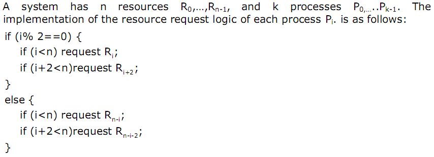

Solution:
Even processes requests
Ri
Ri+2
that is requests resource i and i+2 from beginning

odd process requests
R(n-i)
R(n-i-2)
that is ith and i-2 from last

consider even process as index i and odd as j
Now system can be in deadlock when

1)Ri = Rn-j-2 that is
i = n-j-2
i+j = n-2
and
2) i+2 = n-j that is
i+j = n-2

So we have equation  i+j=n-2
if this is satisfied for any two processes then only deadlock is possible
but we know that i is even and j is odd so
1) i+j is odd and RHS n-2 can be odd only when n is odd and also
2) if number of process are k then i and j has to be < k

Lets see for
1)n=41 and k=19
n-2 = 39 and maximum j can be 19 and i 18 which combine donot ma ke 39 so no deadlock possible
2)when n=21 and k=12
we have n-2 = 19 and i max can be 12 and j 11 which can make the total sum so lets check
when i =10 and j=9 . yes we have deadlock

Scheduling Problems
Things to Remember
In round robin overhead is minimized when time quanta q is maximized
In round robin we use queue order that is does not necessarily
Convoy effect when process needs to use resource for a small time but other process is holding it for long time. FCFS scheduling may suffer convoy effect.
I/O bound process do not use their entire CPU quanta. Better utilization by giving high priority to I/O bound process because of convoy effect


Problem
Use time q=5ms

Solution
Round robin
Shown below is gantt chart with queue


waiting time
total time that is time from arrival to completion - time executing (given in table)
for P1 : 55 - 20 = 35
for p2 : (77-4) - 32= 41
for p3 : 59-14-9 = 36
for p4 : 65-12-11=42
Average 38.5


Shortest Job first
p1 p4 p3 p2
Average = 17.75


Shortest Remaining First


Problem Consider Exponential average to predict length of next CPU burst
1) a=0
then system always uses past history to predict CPU burst without taking in account the recent observation
2)a=.99
then gives very high weight to recent observation and very less to past history and hence almost no memory is required for history


Problem 10 i/o bound process and 1 cpu bound process Each I/O bound process issues I/O operation once for every 1ms of CPU computing and each I/O takes 10ms to complete . context switch overhead = .1ms What is CPU utilization for
1)q=1 ms
Solution CPU utilization is (execution time )/(execution time + overhead time)
for each time quanta system incurs cost of .1 so
1/1.1 = .91
2)q=10ms
A cpu bound process will run for 10ms then a context switch of .1ms total 10.1
each i/o bound process interrupts cpu to context switch for I/O activity after 1ms so total is 1.1 and for 10 process would be 10*1.1
for a execution time of 20ms we have
CPU utilization  = 20/21.1 = .94

Multiprogramming
If a job spends p fraction of time in I/O waiting then
with sequential execution CPU utilization is 1-p
If p =.60 that is its spending 60% of time doing I/O then CPU utilization is only 40%
For multiprogramming with n jobs in the memory
probability that all n processes are waiting for I/O is p^n
CPU utilization is 1-P^n that is probability that at least one process is ready for CPU
this is on the assumption of no cpu overhead

Problem  Suppose two jobs, each of which needs 10 minutes of CPU time, start simultaneously. Assume 50% I/O wait time.
a) How long will it take for both to complete if they run sequentially?
solution Each process takes total of 10 min for I/O + 10 min for CPU that is 20
Total time for complete T = 20min +20min = 40mins
b) How long if they run in parallel?
probability p for which time is spent in I/O
p = 1/2 //50% I/O
CPU utilization = 1-p^2 = .75
T*.75=20


File system
Inode
A files block are scattered randomly
Inodes keeps pointer to data blocks
Each Inode has 15 pointers
First 12 points directly to data block
13th points to indirect block that is block containing data block
14th points to doubly indirect block that is points to block containing 128 addresses of indirectblock
15th points to triply indirect block that is block which points to doubly indirect block
Consider block size of 4K as in unix file system
then 12 direct block pointer can point to 12*4K =48K
if each pointer is of 4 byte then a single block can accomodate 4K/4 = 1K
one indirect can point to 1K*4K =4MB
one doubly indirect 1K*1K*4K


Problem  Let there be 8 direct block pointers, and a singly, doubly, and triply indirect pointer in each inode and  that the system block size and the disk sector size are both 4K. If the disk block pointer is 32 bits, with 8 bits for identifying physical disk, and 24 bits to identify the physical block, then:
1)maximum file size?
Solution each block can hold = 4K/4 = 1K pointers
so direct blocks = 8*4K
single indirect =1K*4K
double indirect =1K*1K*4K
triple indirect = 1K*1K*1K*4K
all sums around 4TB

2)what is maximum file system partition size
Since disk block pointer is 32 bit it can point 2^32 blocks
which includes 8 bits to identify physical disk and 24 bits to identify block
since each block is 4K so total = 16TB

3)assuming inode in memory how many disk access are required for byte position 2634012
since each block is of 4K we find the offset 2634012 modulo 4K = 284  and block number is 643
this block will be addressed by single indirect block so number of access = 1for accessing indirect block and 1 for accessing the actual block =2


Memory Management

.
Remember to always add the time to check cache or tlb even when we have miss.

Problem Assuming single level page table If a memory reference takes 100 nanoseconds, time for memory mapped reference is ?
i)when no TLB
 100 for accessing Page table and 100ns for accessing actual data frame
ii)TLB with access time 15ns and .9 memory hit in TLB
 if page number is present in TLB then 15+100
 if page number not found in TLB then 15+100+100
Hence EMAT = 115*.9 + 215*.1

Problem Consider demand paging with the page table held in registers, memory access times
8 msecs for  page fault if --  empty page is available or the replaced page is not modified,
20 msecs if the replaced page is modified
70% of the time the page to be replaced is modified
100 nsecs memory access time


What is the maximum acceptable page fault rate (P) for an effective access time of no more than 200 nsecs?
Solution
p = page fault rate
and m be percentage of time page is modified then

EMAT >= 1-p(memory access time) + p (m (time to write back dirty page & service fault) + (1-m)(time to service page fault))

.2 >= 1-p(.1)+ p (.70*20000 + .30*8000)

Problem Consider average size of a process as p, size of a page table entry is e, what page size minimizes wasted space due to internal fragmentation and page table?
 Solution
page tables used to store the frame number and control bits is actually a overhead or wasted space
so we calculate wasted space  = space used by page table + space wasted due to internal fragmentation
avg number of pages =p/s
and total size of all pages =pe/s
avg space wasted due to internal fragmentation s/2

so total waste = pe/s + s/2
to find min take derivative
- pe/s^2 + 1/2 = 0
 pe/s^2 = 1/2
 s = sqrt(2pe)

 
Problem Consider the average process size is 128 KB and the number of page entries is 8. What will be appropriate page size
Solution


Page replacement
one has reference time highest means it was referenced farthest on left 
FIFO doesnot depend on the reference time but on the load time
NRU replaces one with r=0,w=0
second chance replaces earliest page with r=0
 If you are given page has been modified written to or dirty then it takes 2 I/O for replacing that page
1 to bring in new page and 1 to write back this page
Virtual to physical address binding takes place during runtime

Consider the following piece of code which multiplies two matrices:
int a[1024][1024], b[1024][1024], c[1024][1024];
multiply()
{
   unsigned i, j, k;
   for(i = 0; i < 1024; i++)
       for(j = 0; j < 1024; j++)
           for(k = 0; k < 1024; k++)
               c[i][j] += a[i,k] * b[k,j];
}
Assume that the binary for executing this function fits in one page, and the stack also fits in one page. Assume further that an integer requires 4 bytes for storage. Compute the number of TLB misses if the page size is 4096 and the TLB has 8 entries with a replacement policy consisting of LRU.
Solution:
1024*(2+1024*1024) = 1073743872
The binary and the stack each fit in one page, thus each takes one entry in the TLB. While the function is running, it is accessing the binary page and the stack page all the time. So the two TLB entries for these two pages would reside in the TLB all the time and the data can only take the remaining 6 TLB entries.
We assume the two entries are already in TLB when the function begins to run. Then we need only consider those data pages.
Since an integer requires 4 bytes for storage and the page size is 4096 bytes, each array requires 1024 pages. Suppose each row of an array is stored in one page. Then these pages can be represented as a[0..1023], b[0..1023], c[0..1023]: Page a[0] contains the elements a[0][0..1023], page a[1] contains the elements a[1][0..1023], etc.
For a fixed value of i, say 0, the function loops over j and k, we have the following reference string:
a[0], b[0], c[0], a[0], b[1], c[0], ¡ a[0], b[1023], c[0]
¡
a[0], b[0], c[0], a[0], b[1], c[0], ¡ a[0], b[1023], c[0]
For the reference string (1024 rows in total), a[0], c[0] will contribute two TLB misses. Since a[0] and b[0] each will be accessed every four memory references, the two pages will not be replaced by the LRU algorithm. For each page in b[0..1023], it will incur one TLB miss every time it is accessed. So the number of TLB misses for the second inner loop is
2+1024*1024 = 1048578
So the total number of TLB misses is 1024*1048578 = 1073743872
Partitions
It is possible to get the new block from the external fragmentation

Problem Consider following hole sizes in memory in  this order: 10KB, 4KB, 20KB, 18KB, 7KB, 9KB, 12KB. Which hole is taken for successive segment
request of 12KB, 10KB, 9KB for
a. First fit?
20KB , 10KB,18KB
b. Best fit?
12KB, 10KB,9KB
c. Worst fit?
20KB,18KB,12KB
d. Next fit?
20KB,18KB,9KB

Secondary storage problems
Problem Consider
10000 RPM spindle speed,
300 Sectors per track,
512 Bytes per sector,
9801 cylinders (tracks per platter side),
24 tracks per cylinder (12 platters),

6ms average seek time,
0.6 ms track-to-track seek time.

Suppose you want to read a 4,608MB file under the following two sets of assumptions:
a) Assume the file is allocated consecutive sectors and tracks on one surface of one of the platters. How long does it take to read the file’s data and what is the average throughput?

Solution
total time to read file =avg seek time+ avg rotational delay + transfer time
rotational delay = 60s/m  / 10000rev/min= 6ms /rev

Calculate bandwidth
total number of bytes in track = total number of sectors * number of bytes per sector = 300*512 = 153600 bytes/sector
bandwidth = number of bytes in track/ rotational delay = 153600/6 bytes/sec
transfer time for x bytes = x/bandwidth = 6*x/156300

For file
Number of blocks in file = 4608000 / 512 blocks = 9000 blocks
or total of  30 tracks

transfer for first track T1 = average seek + average rotational + transfer time
=6ms+3ms+6ms =15
For remaining tracks it would be 6ms transfer time for track + .6ms track to track time
6.6*29
total time =15 +6.6*9
average throughput is 4608000/total time


b) If the individual blocks are randomly scattered over the disk how long will it now
take to transfer this file and what is the average transfer rate?


we read each sector with same avg rotational delay and  avg seek time
so each request is uniform with time of 6ms avg seek time+3ms of avg rotational dealy+6/300 to read a sector =9.02
and there are 9000 such sectors so total time would be 9000*9.02ms

Monday, January 17, 2011

Memory Management - Linking, Loading, Virtual Memory

Loading and Linking

Linker 
A program consist of number of module these are linked to resolve any references between them
static libraries are linked at this time
Takes as input collection of modules are prepares a load module, each symbolic address within each module are changed relative to final load module and this final module is then loaded

Dynamic Linker
It is possible to defer some linkage functions
so load module will contain unresolved references to other programs
Load time Dynamic linking
load module is read into memory and any  unresolved references causes loader to find module, load it and alter the references to relative address
requires dynamic library to loader

Runtim dynamic linking
At the time when call is made to unresolved reference then it is brought in memory
these are shareable module so if its already in the memory linking is done to that.
DLL in windows are example


Loading

Loading is to move the program into memory where it has its associated PCB stack
Absolute loading
all absolute references, module always loaded at same memory location
assignment of addresses can be done by programmer or at compile time

Relative loading
memory address are relative to start of program
compiler or assembler does not produce absolute addresses instead relative
so module can be loaded in any memory location

Dynamic Runtime loading
Since swapping part of program is possible in virtual memory relative address wont work if next time part of program is allocated some other space in memory
so instead of calculating relative address at load time, calculations are deferred  until instruction is actually executed

Segmentation
user and associated data divided into segments
can be different length segments
segment number+offset
all program segments are loaded if no virtual memory
eliminates external segmentation suffers from internal segmentation
visible to user unlike paging
Segment table for each process that keep starting address of segment along with 
size of that segment because segments are of variable size so to check the valid address

TLB
virtual memory access requires at least two memory access one for PTE and one for actual data frame access
 with TLB,high speed cache for PTE, most recently used page table entries can be used to find the frame number If its not there then
1)access page table
2)
If page is in memory then update TLB and CPU genrates physical address
If page table is not in memory(checked with present bit in PTE) then its page fault and 
trap to OS save the state of current process and transfer control to page fault handler
 i)read page from disk more process from running to blocked state
 ii)if no memory available then replace memory page to make space
 iii)update page table and more process from blocked to running

we cannot index TLB with page number because it holds only some of the page table entries so TLB holds both page number and PTE
In TLB  associative mapping is done that is all entries are checked simuiltaneoulsy


Page size
Small page size : less internal fragmentation,optimizes the use of main memory, more pages will be required per process hence larger page table, more pages means only part of page table can be in memory so number of page faults will double including the page table access from disk.
Large page size: disk device transfers efficiently

Virtual Memory
allows only part of process to be in memory
program size can be larger than all available memory
differences:Fetch policy,Demand Paging,Prepaging

Page replacement
Optimal page replacement policy clairvoyant or belady optimal
replace the page for which the time to next reference is longest
least page faults
impossible to implement, so used as benchmark
looks in the future  and finds out of present frames which will be used last or never

Least Recently used policy
replace page in memory that has not been referenced for longest time
decides on  principle of locality
looks in the past and find out of present frames which was used last
so a page reference string S with LRU and  page string reverse(S) with Optimal will give same result
difficult to implement
stack implementation Or counter implementation possible
stack algorithms does not suffers from belady anomaly like optimal and LRU
LRU does nearly as good as Optimal

solving LRU problems
mark the alphabet that are present in memory as they come
look to the left of new alphabet which alphabet in memory is to most left
replace that

First In First Out policy
without looking at the past or future it replaces pages in round robin order
a circular buffer
simplest easy to implement
in other words looks a the present page frames and replace the one that has been for longest time
suffers from belady anomaly that is increasing page frame increases page fault instead of decreasing.

How to solve FIFO page replacement problem
write the alphabet one below other until faults
when page fault cross the first alphabet and place new at last

Thrashing
more paging activity
solution is to use local replacement algorithm instead of global, process cannot steal frames from other process

//go through the counter based implementation and other algorithm that uses reference bits

Tuesday, November 23, 2010

Memory Management - Paging, Swaping, Partitioning

Bring process into main memory from input queue

Fix Partitioning

1. If using equal size partitions, main memory is divided into fix size partitions initially
  • A process whose size <= partition can only be loaded in it. 
  • If program large than partition size program has to design it with overlays reduces the OS overhead.
  • Could lead to internal fragmentation for small size process
  • Process can be loaded into any free partition.
2. If using unequal size partitions, main memory is divided into some unequal partitions initially.
  • so a big process can be allocated the large size partitions and for a small size process we can allocate small partition reducing the internal fragmentation
  • Process can be loaded in the smallest partition within which it fits.
  • A scheduling queue is required for each different size partition which helps swapped out process.
  • It minimizes the wasted memory from internal frag.
  • But could lead to wastage when the large space remains unused because process will be queued for the other partitions that are smallest fit.
Fix partitioning leads to limit on multiprogramming that is active process in the system

Dynamic Partition
Dynamic partition leads to external fragmentation where portion of memory outside the variable size partition are fragmented.
Solution to external fragmentation problem is compaction to move the free space together.Its time consuming process and complete overhead. Processes must be dynamically relocatable for moving them around in memory
If we are to avoid compaction we can make intelligent assignment of process to memory so as to reduce the external fragmentation
Best fit First Fit and Next Fit. First fit is usually best and fastest.
First fit may lead to holes in the front end of memory. More the fragments in the front end more scanning for first fit


Next fit may lead to more external fragmentation leaving the need for compaction.
Best fits leads to many smaller memory holes leading to more frequent compaction.


Buddy System
compromise between two partitioning

Swapping
Consider at t0 we have some n process taking up the complete memory and at time t1 new process with priority higher than all the n process arrives.And we are using some priority scheduling then this process should get the CPU and should be brought in the main memory but since there is no space we need to swap out some process and bring high priority process in memory and then after its finished or some other swaps out we should swap that low priority process in .

Observations
Swapping was used in the old time sharing systems where memory was enough to load only single process so at end of each time quantum new process was brought in memory by swapping present process.
context switch time would be sum of swapping out and again swapping in process or part of it from backing store.
For efficient utilization of CPU each process execution time should be greater than the overhead i.e swap time.
Swapping is very expensive compared to instruction execution.
Swap time is dependent majorly on the transfer time, so if we move only that much portion of main memory which process is actually using, it would reduce the swap time.
We never swap the process with pending I/O or we execute I/O operations into operating system buffers only
Unix uses a variant of swapping, Demand Paging .

Paging
Allows physical address space of the process to be non contagious
Memory is divided into fixed small size chunks called frames and process into pages
Memory wasted in paging is only due to internal fragmentation and that only fraction in  last page of process.
Differs from fixed partitioning in that
 small partitions
 process can be allocated more that one partition
 non contagious allocation for process is possible
In simple partitioning logical address is location relative to beginning of the program and processor translates logical address to physical address
If Page size is decided as 2^n then remaining bits in the relative address of the process would decide the maximum number of pages allowed in page

In case of paging special hardware is used for logical address to physical address translation.Hardware looks up the logical address in the page table to find the physical address

Fig. logical address divided into offset and page number

Page table
stores mapping between logical address and physical address.
Contains one entry for each page of the process
operating system maintains a copy of page table for each process
Context switch time will increase as page table references need to be changed
If a page table entry is 4 byte long that is 32 bits it can address 2^32 physical page frames and if each frame is 4kb then we can address( 2^32)(2^12) = 2^44 bytes

Fig. lookup for virtual address in page table

Page Table Entry PTE

Each page table entry contain page frame address and property bits like a present bit, a dirty or modified bit, address space or process ID information.
Assuming 32-bit physical address with page size of 2^8, we  use 4 bytes for PTE (24 bit physical page number with 8 bits left for control.)

Sharing and Protection
Reentrant code, non self modifying code can be shared between different process
we map the re-entrant portion of code for each process into same physical frames.
the protection bits in the PTE helps perform certain validation like process is not trying to modify the read only page, that each reference to memory is valid.


Types of Page table

 Multilevel Page table
Since each process can occupy a huge amount of virtual memory that is it can have large number of pages that much entry for each process would be too high.To overcome this we store page table in virtual memory rather than real memory that is page table is divided into pages and when a process is running a part of its page table must be in memory including page that is executing

Fig. two level page table organization


All level page table are actually frames stored in the memory
Each entry in the page table is page frame address of size of  PTE


The format for multilevel page table specifies the offsets for each level page table


Consider  three level page table the logical address is divided into four part
1.offset into page directory or fist level page table.each entry points to page frame containing second level entries
2.offset into page middle directory or second level page table
3.offset into third level page table which specifies page frame
4.offset into page frame.


Fig. format of logical address for 3 level page table
Problem 1
Consider 32 bit Physical address 4KB pages, 4GB virtual address space
Number of pages in virtual address space 4GB/4KB = 2^20
Size of page table would be (PTE size) * (number of pages) = 4byte * 2^20 = 2^22 or 4MB
How many virtual pages would be required = (size of page table) / (size of page) = 4MB/4KB = 2^10
So, a top level page table would have 2^10 page table entries and total size would be = (2^10)(4bytes) = 2^12 i.e 4KB.Hence a two level page table would need 4KB more than single level page table. However, not all the second-level tables need to be resident in memory, and page tables are not needed for unmapped virtual memory. Thus the total usage is actually lower, and only the top-level table must be in memory at all times, requiring only 4KB (exactly one page) of physical memory per process.

Problem 2
consider a three level page table 36 bit physical address
2, 9, 9, 12 bits for first level second third and offset of page respectively
page frame size is 4KB and PTE is 4bytes
what will be number of bits required to address each next level table or page frame
Solution
First find Number of bits required to address a single page frame
Number of frames in the main memory =  (2^36/2^12) = 2^24
so we need 24 bits for addressing a page frame
Since each page table at each level is nothing but page frame addressed by PTE we need 24 bits to address each page frame
First level would be addressed by some process pointer after that each page table will have PTE to address next page frame.

Problem 3 consider a three level page table with
10,8,6,8 bits for first level second, third and offset of page respectively
1. What is the size of a page table for a process of 256K
Solution

Fig . three level page table organization for prob 3
Size of page table =(size of 3rd level table * number of third level page tables required + size of 2nd level        table *  number of second level page tables required + size of 3rd level table * number of first level page tables required)

Number of third level page table = (number of virtual pages) / (number of entries third level can hold)
To calculate number of third level page required we first find
how many pages are required by program or present in virtual address space
number of pages in virtual address space = (size of program ) / (page size)
                                                               = (256K)/2^8 = 2^10
so there should be 2^10 entries in the third level page table but each third level page table can hold 2^6 entries only so 2^10/2^6 =16 third level page table will be required

Number of second level page table = (number of third level page table)/(entries in each second level page    table)
                                                     =16/2^8 ~= 1
Number of first level page table = (number of second level page table)/(entries first level can hold)
                                                 = 1/1024 ~= 1
so size of page table = 1024*4*1+256*1+64*4*16

Note if different section are stored differently like data code stack, where two section could get same offset bits at second level then we need to store this in different page table. Number of second page table will change the first level will have three different entry for each section.

Problem 4 Consider system with 36 bit virtual address space and 8k page size with 4byte PTE.
If virtual address space of process is 8G analyze single two and three level page table organizations.
Solution
For first level page table number of page table
//pending

Inverted Page Table (IPT) with hashing
fixed size page table independent of number of processes and number of pages
entry for each physical frame in memory so if physical address is 32 bit with 8 bits for frame then there are 2^24 entries in the page table.
virtual address division = page number + offset but translation would be
page number portion is mapped into hash value which is pointer to inverted page table. since more than one virtual page number can give same hash value chaining technique is used
each page table entry holds page number,process identifier, control bits and chain pointer. Combination of pid and page identifies a page in virtual address space of a process. chain pointer may contains index value to address same table
system implementing IPT has difficulty implementing shared pages


http://www.cs.utexas.edu/users/dahlin/Classes/UGOS/hw/7bsol.html
http://www.ece.cmu.edu/~ece548/handouts/742sln1b.pdf

Monday, November 22, 2010

Process Synchronization in Operating System

Essential criteria to solve critical section problem

1.Mutual exclusion takes care of race condition.
2.Progress means that no process shall be kept from entering its critical section by another process that is stopped outside its critical section i.e if process j blocks in the remainder section it should not affect the entry of i in the critical section.
3.Bound waiting condition guarantees no starvation.If solution provides strict alternation then bounded waiting is inherently satisfied.If access to critical region is arbitrary then starvation is possible.


Mutual exclusion with Hardware 

1. Disabling the interrupts will ensure mutual exclusion but is not practiced for user processes and it is possible only in uniprocessor system. Disabling interrupt would ensure all 3 condition

2. Hardware provides special instruction that allows modification of a word or swap of words atomically
Test and set lock
  • atomic(non interruptible) instruction used to write to a memory location 
  • returns old value.
  • no other process may begin test and set unless first is complete.
  • guarantees mutual exclusion and progress but is prone to starvation. 
  • starvation possible because access to critical region is in arbitrary fashion.  
initially set lock = false;

boolean TSL (boolean &lock) {
 boolean tmp = lock;
 lock = True;
 return tmp;
}

process p0 code
while(TSL(lock));
CS
lock = false;

gets the present value of the lock and sets it to true
Conditions
1.At time t0 process  p0 checks the while condition, TSL(lock) return false as lock is false initially, and sets lock = true, so p0 enters critical section.
2.At time t1>t0 process p1 tries to enter the critical section on call to TSL(lock)  it return true and sets lock to true again, so p1 is not allowed to enter critical section unless p0 executes the lock= false condition in exit section.
3.At time t2>t1process p0 has executed the lock = false and TSL(lock) returns false and p1 enters CS.

Exchange instruction (swap)
swap instruction executes atomically 
initially lock=false
code for process p0
key=true
while(key) swap(lock,key)
cs
lock=false;

Disadvantages of hardware instructions busy waiting(wasting cpu resource) and starvation possible.

Mutual Exclusion with software
1. Using lock variable alone does not ensures mutual exclusion.
Fig. software lock solution

2. Turn variable only.

3. Peterson's Algorithm

Allows two process p0 and p1 to share a single resource without conflict

Fig. peterson solution

1. Mutual Exclusion condition requires us to prove that if both process are checking the last statement of beginning section, that is while loop, only one of the process would be able to enter the critical section.
 Since value of turn can be either 0 or 1, turn value is not changed in CS or in remaining section, if it is 0 process 0 will enter and p1 would still be waiting and similar for p1.

2. For Progress we need to check if process blocks in the remainder section it does not affect the entry of other process in its critical section. In peterson solution process j set the flag[j] = 0 before entering in to its remainder section.so if process j now blocks in its remainder section then also process i can proceed with its critical section unlike in dekker's solution where if process blocks in the remainder section no other process can proceed to critical section.

3. Bounded waiting we need to check if one of the process is waiting that is in the while loop then eventually it will break out of loop and enter critical section.

Problems
All this solution has problem of
1. Busy waiting wasting cpu resource, frequent testing and waiting in while loop.
2. priority inversion problem
consider process p0 has low priority than process p1 and when p0 is in its critical section p1 comes, scheduler assigns CPU to p1 as its high priority process now
p1 gets CPU but cannot proceed because p0 is already in critical section(mutual exclusion)  while
p0 now waits for CPU assigned to process p1
process p1 gets into waiting state, before cpu could be assigned to p0 another process p2 arrives with priority less than p1 but greater than p0 this process will get the cpu
after p2 finishes p0 get the cpu and executes until it exits the critical section then p1 will get cpu
giving us priority inversion, low priority  process running before high priority process.


//here goes wake and sleep and it sproblems

4. Semaphores
Semaphore solution includes a semaphore variable and two atomic operations P(s) and V(s) semaphore is integer number representing the number of available resources.
if it is 0 means no resource is available and process has to wait.
if it is n means n resource are available and can be allocated.
V(s) executes when resource is released to increment the semaphore value.
semaphore does not distinguishes resources.
prevents race condition and deadlock does not guarantees them.

P(s):
while(1){
if s >= n
  s= s-n;
  break;
}

//here goes semaphore with waiting queue and wake up, sleep

semaphore with waiting queue can result in deadlock and also starvation if queue is LIFO


References
http://www.disi.unige.it/person/DelzannoG/SO1/AA0607/peterson.htm
http://en.wikipedia.org/wiki/Peterson%27s_algorithm
www.arl.wustl.edu/~fredk/Courses/cse422/sp03/.../concurrency1.ppt

Sunday, November 21, 2010

Process Scheduling - Operating System Notes

Parameters affecting Process Scheduling decisions

  • CPU utilization decreases by overhead of context switching.
  • Thoughput is number of completed process per unit time and would increase if shortest task are executed firsts
  • Turnaround time is time between submission of process and its completion. Average turnaround time is minimized by executing shortest tasks first
  • Waiting Time time spent in ready queue. It is also minimized when shortest tasks are executed first
  • Response time is increased if context switching is infrequent.
    • response time is the (time of first result from system  - time of process submission)
    • if process is submitted at time t0 and it is scheduled at time tn for for time t then response time is (tn+t) - t0

  • run time of process = Turnaround time - waiting time 
  • cpu utilization for n process = 
                    sum(run time of n process)/{sum(run time of n process) + sum(all contextswitch)}
  • Penalty Rate = turnaround time / run time of process
  • When calculating the turnaround time, waiting time response time, context switching time should be added it may be little when there are fewer context switch but may be significant as context switch increases.
  • So by running shortest jobs  following parameters are optimized .
    • Throughput , turnaround time, waiting time and also CPU utilization because no reorganization of the process queue is required, scheduling overhead is minimal.


Schedulers
  • In Preemptive scheduling transitions from running to ready state .Special hardware is required for preemptive scheduling ,affects the design of kernel

  • The scheduling algorithm in which there is  prioritization or are premptive may lead to starvation because a high priority process will always  hog the cpu.there wont be starvation in non premtive scheduling


First Come First Serve (FCFS) process scheduling
  • cpu utilization is optimal because least possible context switch, on process completion only
  • Throughput, turnaround time, average waiting time and response time not optimal as long process can hog the cpu.

Shortest  Job First (SJF) non premptive process scheduling
  • CPU utilization is optimal
  • Average waiting time is optimal among all non preemptive schedulings
  • throughput is optimal in all non preemptive scheduling


Shortest Remaining Time First (SRTF) premptive SJF process scheduling
  • includes overhead of more context switching and also to position the process in queue
  • CPU utilization not optimal as context switch increases
  • maximum throughput if correct estimates for cpu burst and if context switch negligible
  • Average turnaround time is less than SJF as newly arrived short burst process would be executed first which reduces the waiting time of short burst process.
  • Starvation is possible.


Round Robin (RR) scheduling
  • High context switching hence low cpu utilization
  • optimal response time
  • thoughput between FCFS and SRT
  • no starvation. 
  • round robin is good for short jobs
  • Average turnaround time is greater than in SJF  but average waiting time is less than in SJF
  • If time quantum q is increased ,
    •  Average Turnaround time will decrease
    •  Average waiting time will increase
  • FCFS is RRS with infinite time quantum

Observations about Round Robin scheduling
if we have process p1 with alternating burst of t1 for cpu and t2  for i/o the result of the computation will be visible only after the i/o is done that is response time would be t1+t2 and not t1
Response time if all n process are active then response time = n*(q+s) under certain conditions when q is greater than cpu burst
Two i/o operations of process p1 and p2 are performed in parallel if they wait for different resource, until specified otherwise , that is p2 does not have to wait


Problem 1  Consider n processes sharing the CPU in a round-robin scheduling.  Assuming that each process switch takes s seconds, what must be the quantum size q such that the overhead resulting from process switching is minimized but, at the same time, each process is guaranteed to get its turn at the CPU at least every t seconds (i.e., it is idle for no more than t seconds between time slices)?

Solution

next execution of the process should occur within t seconds

Each process runs for q period and if there are n process
p1 p2 p3 ..... pn p1 p2 ... then p1 turn comes again when it has completed time quanta for remaining process p2 to pn  i.e it would take at most (n-1)q time
So Each process in round robin gets its turn after <= (n-1)q time when we don't consider overheads
but if we consider over head(s) then it would be ns+(n-1)q
So we have ns + (n-1)q <= t
overhead will be reduced when time quantum is maximum allowable i.e,  q = (t-ns)/(n-1)

Problem 2 consider 10 identical process intiated at same time with 15 identical requests
Each request consumes 20 ms of CPU A request is followed by I/O that consumes 10ms The scheduling overhead is 2ms. Find response time for first and last request when
1) time quantum q >= 20ms and
2) time quantum q =10 ms
Solution
Gantt chart
p1 s p2 s p3 s .................p10 s p1 s p2 s ........p10 s p1 s
first requests                               second requests for each process
assuming output recieved after q+s
response time for first process first request = 20 + 2 = 22ms
response time for last process first request =  (20+2) *10 = 220ms
For second run each process first spends 10ms in the I/O wait then makes request
so time quantum q will be spent as
10msec i/o wait + 10 cpu
second request is made after 10ms i/o wait
and result of second request will occur on third run after completing the 10ms CPU
response time for first process second request = 10(on second run)+2+ 9(20+2) + 10(third run) = 10*(20+2)
similarly for all other processes also same time would be incurred

when q=10ms
that is even the first request will not complete on first run
(10+2)*10 // first completion
10+2  //now 20ms CPU for process 1 completes
that is 11*(12)ms for completion of first process first request
For last process it would be (10+2)*10+(10+2)*10 = 240ms
For subsequent request each has to spend one cycle in I/O and then similar way we have to add above time

//pending
link

Refrences
http://en.wikipedia.org/wiki/Scheduling_(computing)
http://read.cs.ucla.edu/111/notes/lec7?do=index
http://people.engr.ncsu.edu/efg/501/f97/solutions.html